UML In a Nutshell
A Quick (and Fun) History of UML
Once upon a time, software development was a bit like the Wild West—no rules, just cowboy coders writing whatever they wanted.
Different teams used different modeling languages to describe their systems, and chaos reigned supreme.
Enter Grady Booch, James Rumbaugh, and Ivar Jacobson—three software engineers with a vision. In 1994, they decided enough was enough and created Unified Modeling Language (UML).
The goal? A single, standardized way to visually represent software architectures.
By 1997, UML became the official standard, backed by the Object Management Group (OMG).
And just like that, software development got a universal language that architects and developers could actually agree on. (Well, mostly… 🤷♂️)
UML vs. Competing Methods
Before UML, different methodologies were used to model software. Some of the biggest rivals included:
| Methodology | Key Features | Why UML Won? |
|---|---|---|
| Booch Method | Object-oriented, used in C++ | Too complex |
| OMT (Object Modeling Technique) | Focused on analysis and design | Lacked standardization |
| OOSE (Object-Oriented Software Engineering) | Use-case driven | UML incorporated its best ideas |
UML took the best parts of these approaches and combined them into one unified system—hence the name!
The Core Concepts of UML
UML consists of 14 different diagram types, but don’t panic! They’re divided into two main categories:
1. Structural Diagrams (What the system is)
- Class Diagram – The blueprint of the system.
- Object Diagram – Like class diagrams, but with real examples.
- Component Diagram – Shows how different parts of the system interact.
- Deployment Diagram – Represents hardware and execution environments.
2. Behavioral Diagrams (What the system does)
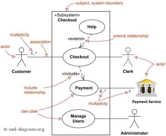
- Use Case Diagram – Shows how users interact with the system.
- Sequence Diagram – Illustrates how objects talk to each other over time.
- Activity Diagram – Think of it as a fancy flowchart.
- State Diagram – Defines how an object behaves in different states.
UML in Action: Code Examples (Sort of…)
Okay, so UML isn’t exactly code, but it’s code-adjacent. Here are some common UML diagrams with examples:
1. Class Diagram Example
| |
2. Use Case Diagram Example
| |
3. Sequence Diagram Example
| |
UML vs. Other Design Approaches
| Feature | UML | Flowcharts | ER Diagrams |
|---|---|---|---|
| Standardized? | ✅ Yes | ❌ No | ❌ No |
| Best for Software? | ✅ Yes | 🤷♂️ Sometimes | ❌ No |
| Shows Relationships? | ✅ Yes | ❌ No | ✅ Yes |
| Used by Engineers? | ✅ Absolutely | ✅ Sometimes | ✅ Yes |
Wrapping Up
UML is the standard for software modeling, used in everything from enterprise applications to indie game development. Whether you love it or find it a bit too formal, one thing’s for sure: it’s here to stay.
If you’re serious about software architecture, UML can help you communicate ideas clearly, making your designs more structured and maintainable. So grab a UML tool and start diagramming like a pro! 💡
Key Takeaways
- UML was created to unify various software modeling techniques.
- It’s visual and helps developers understand complex systems.
- Structural diagrams define system architecture, while behavioral diagrams show interactions.
- UML is a standard, making it better than random flowcharts.
- You don’t have to use all 14 UML diagrams—just the ones that help!